
 18
18


Planetary tailoring is a compact option to basic pinion-and-gear reducers and is used in a wide array of applications to supply high torque.
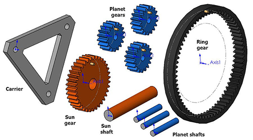
We are going to discuss the setup of a planetary equipment assembly in SOLIDWORKS that will permit us to demonstrate the movement of the 3 drive kinds of this system.To set up our planetary equipment system, first we will insert all of the required elements into a brand-new assembly document:3 x world gears (blue)1 x sun equipment (orange)1 x ring gear (black)1 x carrier3 x carrier shafts1 x sun shaftIn each of the gear part files, pitch circles have actually been produced as construction circle sketches.
The Ring equipment has an extra building circle drawn to guide the path of the Planet equipments.
This will be key to correct movement and will be called the Planet Gear Path.To start putting together the equipment system, we will mate the back face of each equipment Coincident to the Front Plane of the assembly (make certain that none of the parts are repaired in-place, if so right-click the part and select Float).
To speed up this process, utilize the Multiple Mate Mode button, and pick the Front plane as the typical reference.Next, mate the center of the pitch circles on the Ring Gear and Sun Gear to the Assembly origin, they need to both be able to spin.Next, mate the center of the pitch circles of the Planet Gears coincident to the Planet Gear Path sketch.Now, mate the Carrier shafts to the centers of each Planet Gear (Concentric) and flush with their front faces (Coincident).
Get the Carrier in place by including Concentric mates to each Carrier Shaft, and one Coincident mate to bring it flush with the back of among the shafts.Lastly, mate the Sun Shaft into place with another set of concentric and coincident mates (this part is not actually necessary to reveal the movement we want).
We desire the Sun shaft to turn with the Sun gear, so we will also mate Reference Planes together with the Coincident mate to connect the rotation of the 2 parts.Now we are ready for the Gear mates.
Select the Pitch circles made use of each equipment to define the Gear mates.
This will specify the gear ratios, though round faces on the gears could likewise be used and ratios can be by hand overwritten.
Include Gear mates between the 3 Planet gears and the Ring gear and one gear mate in between a single Planet gear and the Sun gear (this is all that is required for the complete equipment movement).
While making the Gear mates, make certain to evaluate each and guarantee that the spin instructions are right.
Utilize the Reverse checkbox in the Mates Property Manager to repair if required.
Also, do not fret about making the equipment teeth mesh properly (we will fix this next.) To group the equipment mates into a folder: shift-select the Gear mates, right-click, and choose Add to New Folder.
Drag it to the top of the Mates folder for ease of access.Next, we will make another group of mates to assist position the equipment teeth correctly, this can be done by developing Parallel (or Angle) mates between reference airplanes on the equipments and recommendation planes on the assembly.
Depending upon how the equipments were produced, this must get the teeth to mesh properly, in this assembly the Top aircrafts are lined up with teeth and the Front airplanes aligned with gaps, so getting accurate positioning is quickly achieved with parallel mates.
Utilizing mates for the positioning is more suitable to dragging them into place since they can be utilized in the future if realignment is needed.
Don’& rsquo; t forget to add an additional mate to line up the Carrier.
Group these mates into a folder too.
As soon as aligned, reduce the whole folder.Now it’& rsquo; s time to develop configurations for the 3 modes of motion.
For each configuration a component will be fixed in place, before repairing any part make sure to unsuppress the alignment mates to ensure these elements are in the appropriate position and then suppress the alignment mates when again.
Include a configuration called “& ldquo; Ring Gear Fixed.
& rdquo; Right-click the Ring Gear and select Fixed, This Configuration only.To test movement, turn the planetary gears by the Carrier for best results.For the second setup, copy and paste the Default Configuration and rename it “& ldquo; Sun Gear Fixed.
& rdquo; Align the gears and fix the Sun Gear in this configuration only.Repeat the procedure, calling the third configuration “& ldquo; Carrier Fixed & rdquo; and fix the provider just because configuration.If at any point after switching configurations the gear teeth do not mesh correctly, very first suppress the equipment mates and then unsuppress the positioning mates.
After the gears are realigned, you can as soon as again reduce the positioning mates and unsuppress the gear mates.
Remember that the gear teeth do not need to mesh correctly for the motion of the planetary gear system to be observed, though it will impact assessment tools such as disturbance detection.Check out our site to learn more and discover other SOLIDWORKS features or contact us at Hawk Ridge Systems today.
Thanks for reading!Sponsored material by Hawk Ridge SystemsThe post How to Set Up a Planetary Gear Motion with SOLIDWORKS appeared first on The Robot Report.